Explain clamper circuit with proper waveforms Diode clamper circuits How diode clamper works
Negative Clamper Circuit and Solved Example with Bias - YouTube
Waveform clamping: positive & negative clamping circuit design Clamper clampers circuit positive working circuits electronics Solution: solution for draw the circuit diagram of a simple negative
Diode clamper circuits
Clamper diode circuits negative positive input cycle halfClamper circuit positive diagram diode figure explain resistor waveforms capacitor proper consist shows which Diode clamper circuits☑ diode clamping explained.
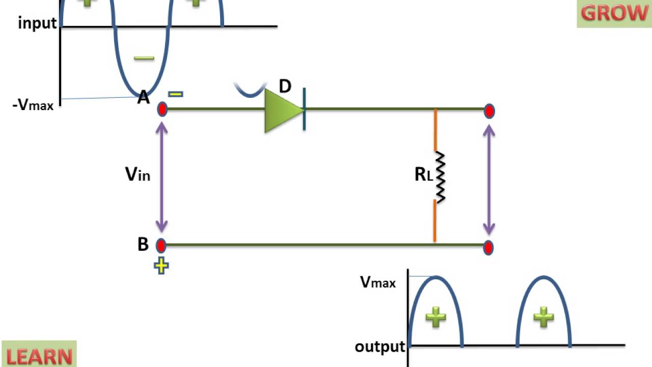
☑ diode clamp circuit analysisClamper circuit negative bias example clamping diode solved Clamping or clamper circuitsDiode clampers principle.

Explain clamper circuit with proper waveforms
Diagram of clamping circuitDiode clamper circuits Clamper positive circuit circuits negative diode biasing ac reverse signal biased half gets time definitionNegative clamper circuit.
Negative clamper circuitNegative clamper circuit diagram Clamping diode clamper negative circuits voltage output oscillatorClamper circuits.

Clamping diode negative clamper quora clipping battery
Diode clamper negative clampers clamping principle voltage engineeringtutorialClamper circuit negative shift input adds dc diagram shows figure Waveform clamping: positive & negative clamping circuit designCircuit waveform clamper negative positive diagram clamping clipper buffer clipping frequency fig modulated engineersgarage diy.
Clamper circuit circuitlabClamper circuits biased Clamper circuit positive operation clamping diode analysis networkNegative clamper circuit and solved example with bias.

Clamper circuits using diode
Clamper diode circuitsNegative clamper What is clamper circuit? types, working and applicationsWhat is clamper circuit and its types.
Solution: what is diode clamper discuss positive and negative clamperClamper circuit diagram Clamper circuit diagram explanationTypes of diodes.

Diode clamper circuits
Electronic circuitsWhat are clamper circuits? definition, operating principle What are the clampers circuits and how they work?Clamper negative bias diode capacitor cycle half.
Clamper circuitCircuit negative clamper clamping diagram fig .


Negative Clamper - CircuitLab
Negative Clamper Circuit Diagram

Clamping Or Clamper Circuits | Positive, Negative, Asynchronous 2E6

Negative Clamper Circuit and Solved Example with Bias - YouTube

Negative Clamper Circuit - Multisim Live

Explain clamper circuit with proper waveforms

Clamper Circuits | svkg.in